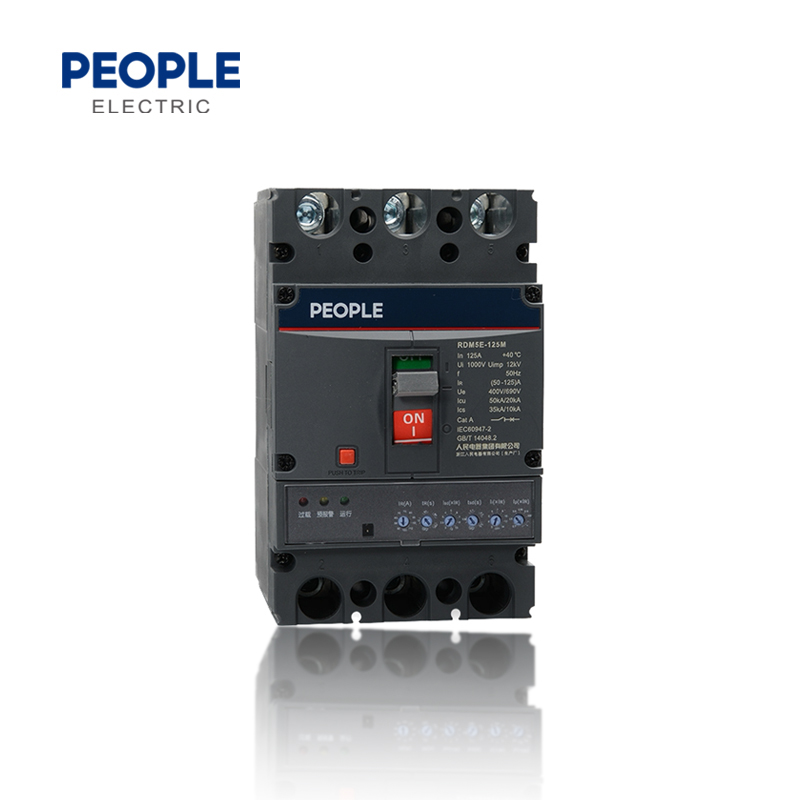
RDM5E series electronic molded case circuit breaker. The circuit breaker is applicable to the distribution network with AC 50Hz, rated insulation voltage of 1000V, rated working voltage of 690V and below, and rated working current of 800A and below. It is used to distribute electric energy and protect the line and power supply equipment from overload, short circuit, undervoltage and other faults.
RDM5E series Circuit breaker with rated current of 630A and below. It can also be used to protect the motor. Under normal conditions, the circuit breaker can be used for infrequent line switching and infrequent motor starting.
RDM5E series circuit breaker has the functions of overload long time delay inverse time limit, short circuit short time delay inverse time limit, short circuit short time delay definite time limit, short circuit instantaneous and undervoltage protection, which can protect the route and power supply equipment from damage.
The circuit breaker has isolation function, and its symbol is
The product conforms to IEC60497-2/GB/T14048.2 standard.
RDM5E | 125 | M | P | 4 | 4 | 0 | 2 | Z | R | ||
Product code | Frame Size | Breaking capacity | Operation mode | Poles | Release mode | Accessories code | Use code | Product category | Wiring mode | ||
Electronic molded casecircuit breaker |
125 250 400 800 |
M: Medium breaking type H: High breaki ng type |
No code: handledirect operation Z. Turn handle operation P: Electric operation |
3:3 poles 4:4 poles |
Release mode code 4: Electronicrelease |
See Table1 for accessory code | No code: circuit breaker for distribution 2: Circuit breaker for motor protection |
No code: basic type Z: Intelligent communication type 10:Fire protection type |
No code: front-plate wiring R: wiring behind the board PF: plug-in front-plate wiring PR: plug-in rear-plate wiring |
Remarks:
1) It has overload thermal memory function: overload thermal memory function, short circuit (short time delay) thermal memory function.
2) Communication function: standard RS485 interface, Modbus field bus protocol. It is realized through plug-in accessories. See the
following table for the configuration of communication accessories:
No | Description | Accessory function | ||||||
1 | Communication shunt alarm accessories | Communication+shunt+overload alarm without tripping+reset button+work indication | ||||||
2 | Status feedback communication attachment | Four remote communication+reset button+work indication | ||||||
3 | Prepayment attachment | Prepayment control+work instructions |
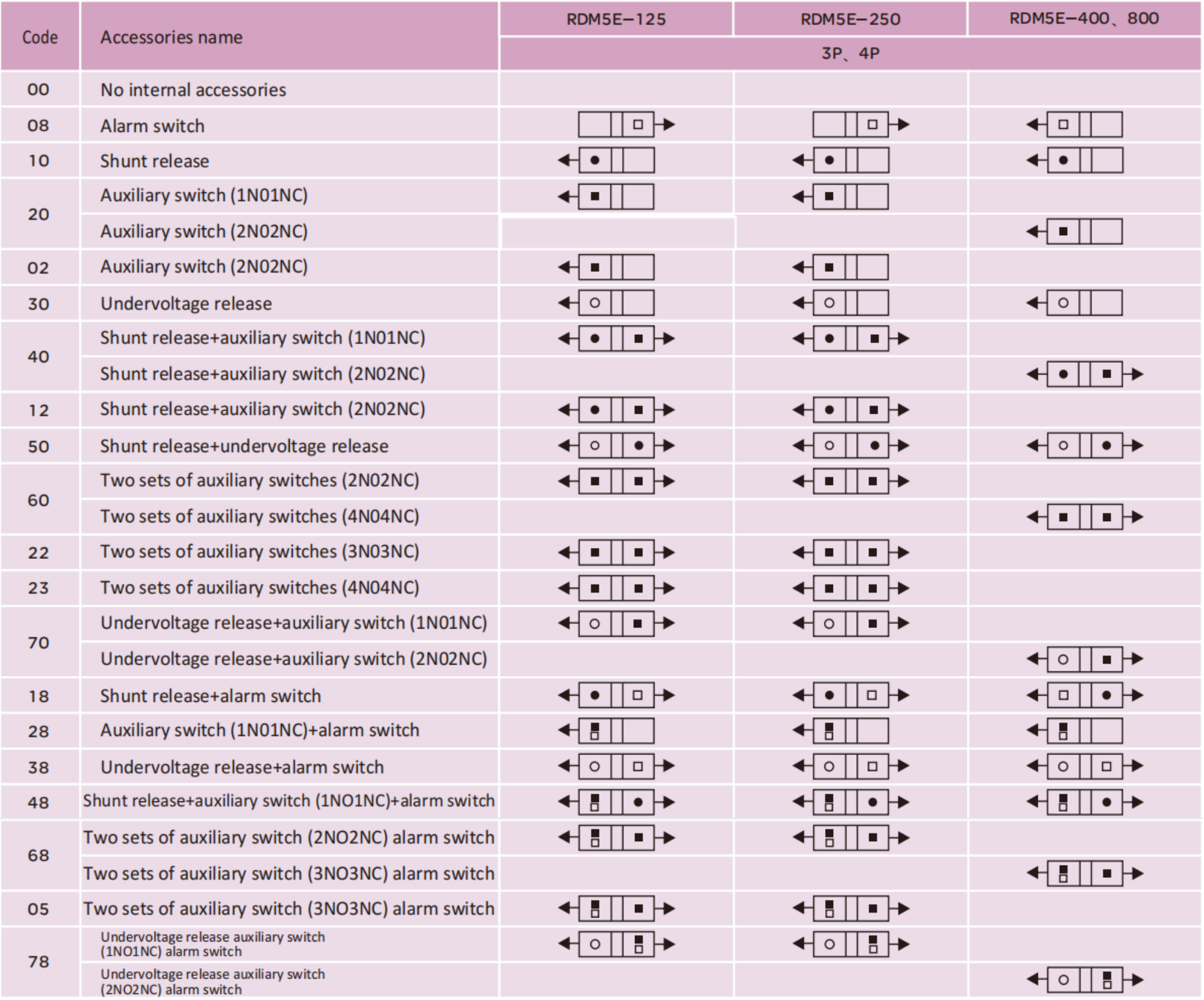
£Alarm switch | █ Auxiliary switch | ●Shunt release | ○Undervoltage release | →Leader direction | Left side installation | Handle | Right side nstallation |
□The ambient air temperature shall not exceed+40℃ , and the average temperature within 24h shall not exceed+35 .The lower limit of ambient air temperature is - 5℃ .
□The altitude of the installation site shall not exceed 2000m.
□ When the maximum temperature is+40℃ , the relative humidity of the air shall not exceed 50%. Higher relative humidity can be allowed at lower temperatures, such as 90% at 20℃ . Special measures shall be taken for occasional condensation on products due to temperature changes.
□ The installation category of the main circuit of the circuit breaker is Class III, and the installation category of the auxiliary circuit and control circuit not connected to the main circuit is Class II
□ The pollution level is Level 3.
□ Use category is A or B.
□ The inclination of the installation surface of the circuit breaker shall not exceed ± 5℃ ;
□ The circuit breaker shall be installed in a place without explosion hazard, conductive dust, corrosion of metal and damage of insulation;
□ The product shall be handled with care during transportation, and shall not be inverted to avoid severe collision.
Intelligent controller is the core component of molded case circuit breaker. It is applied to motor protection or power distribution protection to realize the integration of measurement, protection, control and communication functions, so as to protect the line and power supply equipment from overload, short circuit, grounding and other fault hazards.
MCU microprocessor controller is adopted, with stable and reliable performance: the intelligent controller can provide power supply, as long as one phase is powered on, when the current is not less than 35% of its rated value, it can ensure the normal operation of the protection function;
□ Selective cooperation with three-section protection: use circuit breaker of category B and other short circuit protection connected in the same circuit. The device has selective coordination under short circuit conditions; Setting of overload long delay inverse time limit, short circuit delay (inverse time limit, definite time limit), short circuit instantaneous and other protection function parameters;
□ It has three parameter settings of action current and action time, and can be adjusted in 4-10 gears: users can adjust according to the load current requirements; the controller can be set and adjusted, and the corresponding functions can be selected to be closed according to the user’s requirements (customized functions, which need to be ordered by the us
er When specified);
□ Large current instantaneous tripping function: when the circuit breaker is closed and running, in case of short circuit large current ( 20 Inm), the magnetic tripping mechanism of the circuit breaker can directly trip, and the double protection is more reliable and safe;
□ With tripping test (test) function: input DC 12V voltage to test the action characteristics of circuit breaker;
□ Fault self-diagnosis function: protect and detect the working state and operation of the intelligent controller itself;
□ With pre-alarm indication and overload indication: when the load current reaches or exceeds the setting value, the light guide column will lead out the light source;
□ Dual air gap technology of magnetic flux converter: more reliable and stable operation, no misoperation, reliable tripping and low power;
□ High protection accuracy: overload protection, short circuit short delay protection action current accuracy ± 10%; The accuracy of short-circuit instantaneous protection value is ± 15% depending
on the action current;
□ Interchange ability of installation: the overall dimensions and installation dimensions are the same as those of RDM1 series plastic case circuit breaker.
□ Dual passive signal output function: for signal (or alarm), with capacity of AC230V3A;
□ With fire shunt function: overload alarm does not trip (a pair of passive contacts are provided) and shunt trip function is provided;
□ Communication function: standard RS485, Modbus field bus protocol;
Rated current of shell frame grade Inm (A) | 125 | 250 | 400 | 800 | |||||
Rated current In (A) | 32、63、125 | 250 | 400 | 630、800 | |||||
Current setting value IR (A) | (12.5~125)+Close | (100~250)+Close | (160~400)+Close | (250~800)+Close | |||||
Breaking capacity level | M | H | M | H | M | H | M | H | |
Number of poles | 3P、4P | ||||||||
Rated frequency (Hz) | 50 | ||||||||
Rated insulation voltage Ui (V) | AC1000 | ||||||||
Rated impulse withstand voltage Uimp (V) | 12000 | ||||||||
Rated working voltage Ue (V) | AC400/AC690 | ||||||||
Arcing distance (mm) | ≤50 | ≤50 | ≤100 | ≤100 | |||||
Short-circuit breaking capacity level | M | H | M | H | M | H | M | H | |
Rated limit short-circuit brea king capacity Icu (kA) |
AC400V | 50 | 85 | 50 | 85 | 65 | 100 | 75 | 100 |
AC690V | 35 | 50 | 35 | 50 | 42 | 65 | 50 | 65 | |
Rated operating short-circui t breaking capacity Ics (kA) |
AC400V | 20 | 20 | 20 | 20 | 20 | 20 | 20 | 20 |
AC690V | 10 | 10 | 10 | 10 | 15 | 15 | 15 | 15 | |
Rated short-time withstand current Icw (kA/1s) |
1.5 | 3 | 5 | 10 | |||||
Use category | A | A | B | B | |||||
Compliance with standards | IEC60497-2/GB/T14048.2 | ||||||||
Applicable working ambient temperature | -35℃~+70℃ | ||||||||
Electrical life (times) | 8000 | 8000 | 7500 | 7500 | |||||
Mechanical life (times) | 20000 | 20000 | 10000 | 10000 | |||||
Front panel connection | █ | █ | █ | █ | |||||
Back panel connection | █ | █ | █ | █ | |||||
Plug-in wiring | █ | █ | █ | █ | |||||
Undervoltage release | █ | █ | █ | █ | |||||
Shunt release | █ | █ | █ | █ | |||||
Auxiliary contact | █ | █ | █ | █ | |||||
Alarm contact | █ | █ | █ | █ | |||||
Electric operating mechanism | █ | █ | █ | █ | |||||
Manual operating mechanism | █ | █ | █ | █ | |||||
Intelligent control module | █ | █ | █ | █ | |||||
Test power module | █ | █ | █ | █ | |||||
Communication function | █ | █ | █ | █ | |||||
Time setting | █ | █ | █ | █ |
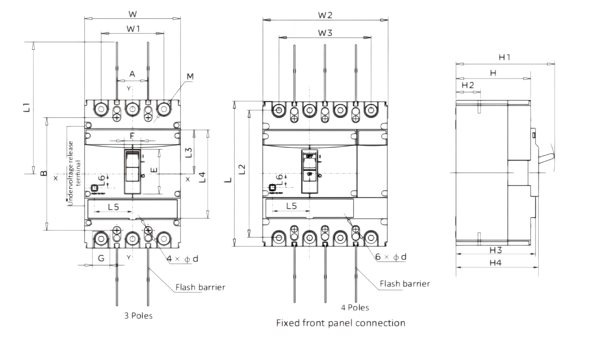
See Figure 1 for the overall dimensions of the front-plate wiring (X-X and Y-Y are the center of the circuit breaker)
Model | Front panel connection | Button location |
|||||||||||||||||
W | W1 | W2 | W3 | L | L1 | L2 | L3 | L4 | H | H1 | H2 | H3 | H4 | E | F | G | L5 | L6 | |
RDM5E-125 | 92 | 60 | 122 | 90 | 150 | 125 | 132 | 43 | 92 | 82 | 112 | 29 | 93 | 96 | 43 | 19 | 18 | 22 | 16 |
RDM5E-250 | 107 | 70 | 142 | 105 | 165 | 136 | 144 | 52 | 104 | 85 | 115 | 23 | 90.5 | 94 | 50 | 19 | 23 | 42.5 | 15.5 |
RDM5E-400 | 150 | 96 | 198 | 144 | 257 | 256 | 224 | 9 | 159 | 99 | 152 | 38 | 104 | 115 | 80 | 42 | 1 | 57.5 | 30 |
RDM5E-800 | 210 | 140 | 280 | 210 | 280 | 240 | 243 | 80 | 178 | 102 | 158 | 41 | 112 | 122 | 82 | 42 | 44 | 53 | 24.5 |