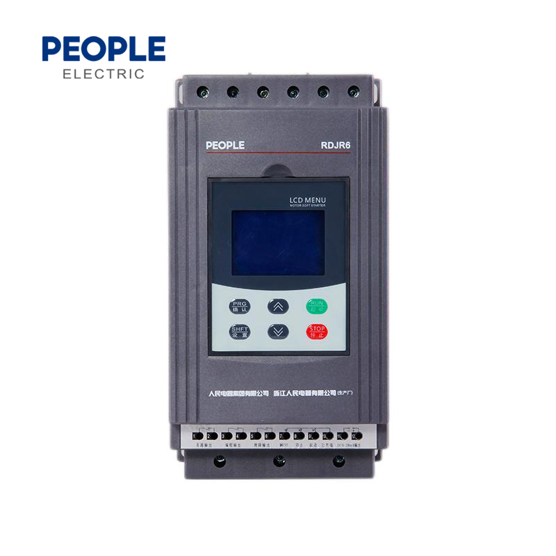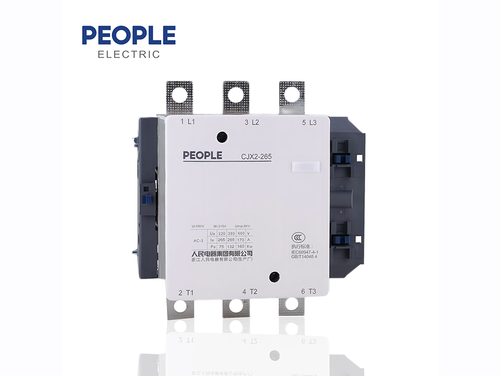
Soft starter is a motor control device that integrates soft start, soft stop, light load energy saving and multiple protection functions It mainly consists of three-phase anti parallel thyristors connected in series between the power supply and the controlled motor and its electronic control circuit Different methods are used to control the conduction angle of three-phase anti parallel thyristors, so that the input voltage of the controlled motor changes according to different requirements.
1.Adopts the Microprocessor digital auto control, it has great electromagnetic performance. soft starting, soft stopping or free stopping.
2.The starting voltage, current, soft-start and soft-stop time can be adopted according to different loads for reducing the shock of starting current. stable performance, easy operation, direct display, small volume, digital set, has tele-control and external control functions.
3.Have protection against phase-loss, overvoltage, overload, overcurrent, overheating.
4.Have functions of input voltage display, operating current display, failure self-inspection, fault memory. has 0-20mA simulation value output, can realize motor current monitoring.
AC induction-motor has advantages of low-cost,high reliablity and infrequent maintainance.
Disadvantages:
1.starting current is 5-7 times higher than rated current.And it requires that power prid has large margin,and it also would reduce the working life of electrical control device,improving maintainance cost.
2.starting torque is doule-time of normal starting torque to cause the load shock and drive components damage. The RDJR6 soft-starter adopts the controllable thyistor module and phase shift technology to improve the voltage of motor regularly.And it can realize the requirement of motor torque,current and load by control parameter. RDJR6 series soft-starter adopts microprocessor to control and realize functions of soft-starting and soft-stopping of AC asynchronous motor,has complete protection function,and widely used in Motor drive equipment in the fields of metallurgy,petroleum,mine,chemical industry.
Production specification
Model No. | Rated power (kW) | Rated current (A) | Applicative motor power (kW) | Shape size (mm) | Weight (kg) | Note | |||||
A | B | C | D | E | d | ||||||
RDJR6-5.5 | 5.5 | 11 | 5.5 | 145 | 278 | 165 | 132 | 250 | M6 | 3.7 | Fig2.1 |
RDJR6-7.5 | 7.5 | 15 | 7.5 | ||||||||
RDJR6-11 | 11 | 22 | 11 | ||||||||
RDJR6-15 | 15 | 30 | 15 | ||||||||
RDJR6-18.5 | 18.5 | 37 | 18.5 | ||||||||
RDJR6-22 | 22 | 44 | 22 | ||||||||
RDJR6-30 | 30 | 60 | 30 | ||||||||
RDJR6-37 | 37 | 74 | 37 | ||||||||
RDJR6-45 | 45 | 90 | 45 | ||||||||
RDJR6-55 | 55 | 110 | 55 | ||||||||
RDJR6-75 | 75 | 150 | 75 | 260 | 530 | 205 | 196 | 380 | M8 | 18 | Fig2.2 |
RDJR6-90 | 90 | 180 | 90 | ||||||||
RDJR6-115 | 115 | 230 | 115 | ||||||||
RDJR6-132 | 132 | 264 | 132 | ||||||||
RDJR6-160 | 160 | 320 | 160 | ||||||||
RDJR6-185 | 185 | 370 | 185 | ||||||||
RDJR6-200 | 200 | 400 | 200 | ||||||||
RDJR6-250 | 250 | 500 | 250 | 290 | 570 | 260 | 260 | 470 | M8 | 25 | Fig2.3 |
RDJR6-280 | 280 | 560 | 280 | ||||||||
RDJR6-320 | 320 | 640 | 320 |
Diagram
Functional parameter
Code | Function name | Setting range | Default | Instruction | |||||||
P0 | initial voltage | (30-70) | 30 | PB1=1, Voltage slope model is effective; when PB setting is current mode, initial voltage default value is 40%. | |||||||
P1 | soft-starting time | (2-60)s | 16s | PB1=1, Voltage slope model is effective | |||||||
P2 | soft-stopping time | (0-60)s | 0s | Setting=0, for free stop. | |||||||
P3 | program time | (0-999)s | 0s | After receiving commands, using countdown type to delay start after P3 setting value. | |||||||
P4 | start delay | (0-999)s | 0s | Programmable relay action delay | |||||||
P5 | programm delay | (0-999)s | 0s | After overheat removing and P5 setting delay, it was into ready state | |||||||
P6 | interval delay | (50-500)% | 400% | Be related with PB setting,when PB setting is 0, default is 280%,and amend is vaild. When PB setting is 1,limiting value is 400%. | |||||||
P7 | limited start current | (50-200)% | 100% | Use to adjust the motor overload protection value, P6, P7 input type depends on P8. | |||||||
P8 | Max operatinal current | 0-3 | 1 | Use to setting current value or percents | |||||||
P9 | current display mode | (40-90)% | 80% | Lower than setting value, failure display is “Err09″ | |||||||
PA | undervoltage protection | (100-140)% | 120% | Higher than setting value,failure display is “Err10″ | |||||||
PB | starting method | 0-5 | 1 | 0 current-limited, 1 voltage,2 kick+current-limited, 3 kick+current-limit, 4 current-slope, 5 dual-loop type | |||||||
PC | output protection allow | 0-4 | 4 | 0 primary, 1 min load, 2 standard, 3 heavy-load, 4 senior | |||||||
PD | operational control mode | 0-7 | 1 | Use to select panel, external control terminal settings. 0, only for panel operating, 1 for both panel and external control terminal operating. | |||||||
PE | auto-reboot choice | 0-13 | 0 | 0: forhibid, 1-9 for auto-reset times | |||||||
PF | parameter amend allow | 0-2 | 1 | 0: fohibid, 1 for allowable part amended data, 2 for allowable all amended data | |||||||
PH | communication address | 0-63 | 0 | Use to communication of multiply soft-starter and upper device | |||||||
PJ | program output | 0-19 | 7 | Use to programmable relay ouput(3-4)setting. | |||||||
PL | soft-stop current limited | (20-100)% | 80% | Use to P2 soft-stopping current-limited setting | |||||||
PP | motor rated current | (11-1200)A | rated value | Use to input motor nominal rated current | |||||||
PU | motor undervoltage protection | (10-90)% | forbid | Use to seting motor undervoltage protection functions. |
Failure instruction
Code | Instruction | Problem and solution | |||||||||
Err00 | no failure | Failure of undervoltage, overvoltage,overheating or transient stop terminal open had been fixed. And the panel indicator is lighting, press “stop” button to reset, then starts the motor. | |||||||||
Err01 | external transient stop terminal is open | Check if external transient terminal7 and common terminal10 are short-circuit or NC contact of other protection devices are normal. | |||||||||
Err02 | soft-starter overheating | Radiator temperature is exceed 85C,overheating protection,soft-starter starts the motor too frequent or motor power is not applicable to soft-starter. | |||||||||
Err03 | starting overtime | Starting setting data is not applicative or load is too heavy, power capacity is too small | |||||||||
Err04 | input phase-loss | Check if input or major loop has fault, or if bypass contactor can break and make circuit normally, or if the silicon control is open | |||||||||
Err05 | output phase-loss | Check if input or major loop has fault, or if bypass contactor can break and make circuit normally, or if the silicon control is open, or if motor connection has some faults. | |||||||||
Err06 | imbalanced three-phase | Check if input 3-phase power and motor has some errors, or if current-transformer gives signals out. | |||||||||
Err07 | starting overcurrent | If load is too heavy or motor power is applicatble with soft-starter, or setting value PC(output protection allowed)setting falut. | |||||||||
Err08 | operational overload protection | If load is too heavy or P7, PP setting falut. | |||||||||
Err09 | undervoltage | Check if input power voltage or setting date of P9 is error | |||||||||
Err10 | overvoltage | Check if input power voltage or setting date of PA is error | |||||||||
Err11 | setting data error | Amend setting or press on “enter” button to start for resetting | |||||||||
Err12 | short-circuit of loading | Check if the sillicon is short-circuit, or load is too heavy,or motor coil is short-circuit. | |||||||||
Err13 | restart connecting error | Check if external starting terminal9 and stop terminal8 are connecting according to two-line type. | |||||||||
Err14 | external stop terminal connection error | When PD setting is 1, 2, 3, 4 (allow to external control), external stop terminal8 and common terminal10 are not short-circuit. Only they were short-circuit, motor can be started. | |||||||||
Err15 | motor underload | Check motor and load error. |
Model No.
External control terminal
External control terminal definition
Switch value | Terminal code | Terminal function | Instruction | |||||||
Relay output | 1 | Bypass output | control bypass contactor, when soft starter starts successfully, it is NO contact without power supply, capacity: AC250V/5A | |||||||
2 | ||||||||||
3 | Programmable relay output | output type and functions are setted by P4 and PJ, it is NO contact without power supply, capacity: AC250V/5A | ||||||||
4 | ||||||||||
5 | Failure relay output | when soft starter has failures, this relay closed, it is NO contact without power supply, capacity: AC250V/5A | ||||||||
6 | ||||||||||
Input | 7 | Transient stop | soft-starter starting normally, this terminal must be shorten with terminal10. | |||||||
8 | Stop/ reset | connects with terminal 10 to control 2-line,3-line, according to connection method. |
||||||||
9 | Start | |||||||||
10 | Common terminal | |||||||||
Analog output | 11 | simulation common point (-) | output current of 4 times rated current is 20mA,it also can be detected by external DC meter, It can output load resistance Max is 300. | |||||||
12 | simulation current output (+) |
Display panel
Indicator | Instruction | ||||||||
READY | when power on and ready state, this indicator is light | ||||||||
PASS | when bypass operating, this indicator is light | ||||||||
ERROR | when failure is happening, this indicator is light | ||||||||
A | setting data is current value, this indicator is light | ||||||||
% | setting data is current precentage, this indicator is light | ||||||||
s | setting data is time, this indicator is light |
state indicator instruction
Button instruction instruction
RDJR6 series soft-starter has 5 kinds operational state: ready, operation, failure, start and stop,ready, operation, failure
has relative indicator signal. Instruction see above Table.
In the soft-starting and soft-stopping proceessing, it can not set data, only if it is under other state.
Under setting state, setting state would quit the setting state without any operating after 2mins.
First press on “enter” button, then charged andstarting starter. After listening the alert sound, then it can reset the
data back factory value.
Appearance and mounting dimension
Application diagram
Normal control diagram
Instruction:
1.External terminal adopts two line tcontrol type.when KA1 closed for starting,open for stopping.
2. soft-starter which above 75kW needs to control bypass contactor coil by middle relay,because of limited drive capacity of soft-strater internal relay contact.
12.2 one common and one standby control diagram
12.3 one common and one standby control diagram
Instruction:
1. In the diagram, external terminal adopts two-line type
(when 1KA1 or 2KA1 is closed, it starts.when they are breaking,it stops.)
2. Soft-starter above 75kW needs to control bypass contactor coil by middel relay because of limited drive capacity of soft-starter internal middle relay contact.