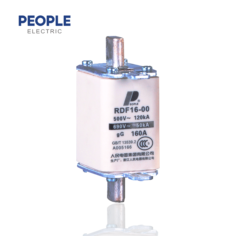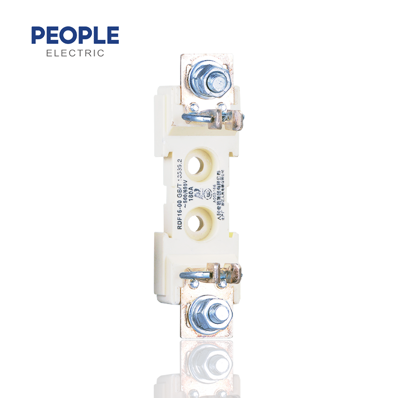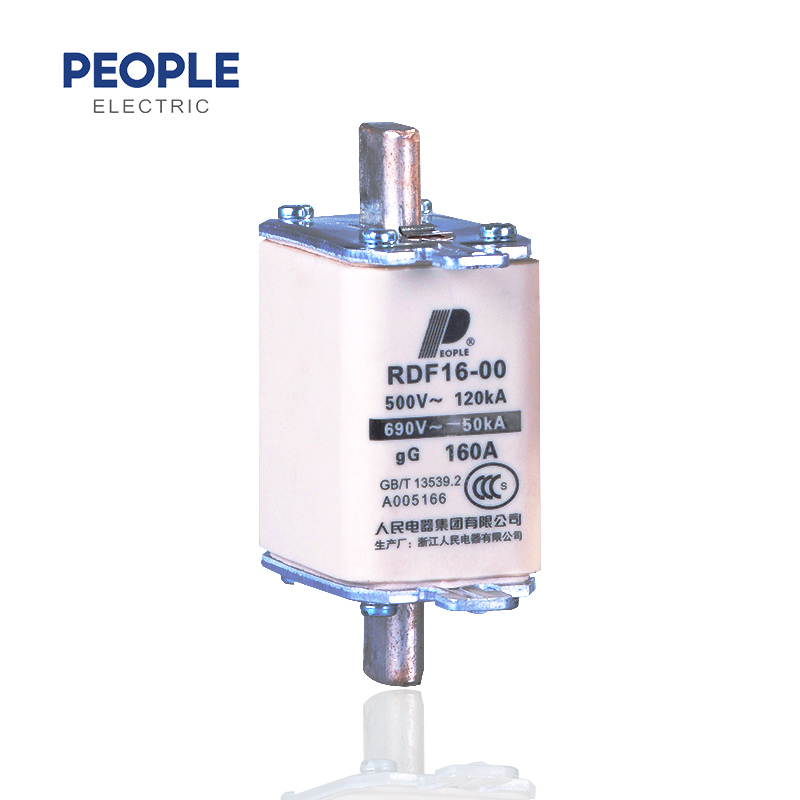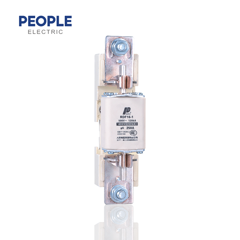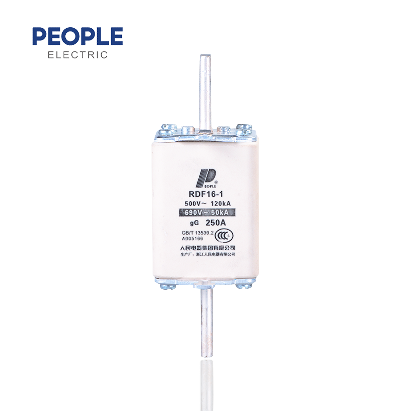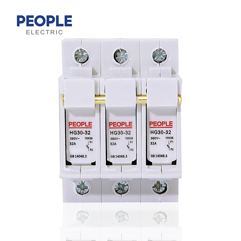
RDF16 series of fuse is consisted of the fuse link and fuse base, remove the fuse link can choose the fusion loading component/handle.
The fuse link is consisted of fuse tube, melt, filler and indicator. The variable cross-section melt of pure copper belt or wire is sealing into the high strength fuse tube, there filled into the fuse tube with the high purity of quartz sand that is processed by chemical as the arcing medium. Two ends of the melt are spot welded to be firmly electric connected with the end plate (or connecting plate), which forms the knife contact plug-in type structure. The fuse link can be with fusing indicator or impactor, it can display fusing(indicator) or convert to various signals and automatically change-over the circuit (impactor) when the melt is fusing.
The fuse base is combined with flame – retarded DMC plastic baseboard, and the wedged type static contacts, which appears open type structure. The front plate wiring terminal is to be connected with the external wire by the screw. There pre-remains two installation holes. The whole fuse holder has the advantages of good heat dissipation effect, high tensile strength, reliable contacts and convenient operation, etc. The fusion loading component/handle is formed by the thermosetting plastic film, which is good insulation performance,simple structure and freely operate.
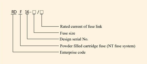
Model No.
Normal operating condition and installation condition
1. Ambient temperature:-5℃~+40C,average value within 24h does not exceed+35C, and the average value within one year should be less than this value.
2. Altitude of installation place does not exceed 2000m
3 . Atmosphere condition
The air is clean, and its relative humidity does not exceed 50% when the ambient temperature is at 40 C.It is allowed relatively high humidity at the relatively low
temperature, for example, the relative humidity can reach 90% when 20℃,and it should take consideration of the condensation produced on the surface of product that is due to the temperature variation.
4. Voltage
When the rated voltage is 500V,the maximum value of system voltage does not exceed
110% of fusc’s rated voltage; When the rated voltage is 690V, the maximum value of system does not exceed 105% of fuse’s rated voltage.
Note: the fuse link is fusing in a significantly lower than the rated voltage, the fuse indicator or fuse impactor may not act.
5. Installation category:Ⅲ
6 Grade of pollution: not less than 3
7 Installation position
This series of fuse can be vertically, horizontally or obliquely installed at those operation occasions of without obvious shake, impact vibration.
Note: if the fuse is used in the different from the normal installation specified condition, it should be negotiated with the manufacturer.
Size | Code | ||||||
A | B | C | D | E | F | G | |
00C | 78.5 | 54 | 21 | 40.5 | 6 | 42.5 | 15 |
0 | 78.5 | 54 | 29 | 48 | 6 | 60 | 15 |
1 | 135 | 70 | 48 | 48 | 6 | 62 | 20 |
2 | 150 | 70 | 60 | 60 | 6 | 72 | 25 |
3 | 150 | 70 | 67 | 68 | 6 | 82 | 32 |
Size | Code | ||||||
A | B | C | D | E | F | G | |
00C | 78.5 | 54 | 21 | 40.5 | 6 | 42.5 | 15 |
00 | 78.5 | 54 | 29 | 48 | 6 | 60 | 15 |
1 | 135 | 70 | 48 | 48 | 6 | 62 | 20 |
2 | 150 | 70 | 60 | 60 | 6 | 72 | 25 |
3 | 150 | 70 | 67 | 68 | 6 | 82 | 32 |
Size | Rated current A | Max.rated power consumption Pn W | |||
IEC 60269 | EN 60269 | VDE 063 | PEOPLE | ||
00 | 16 | 12 | 12 | 7.5 | 2.1 |
25 | 12 | 12 | 7.5 | 2.5 | |
32 | 12 | 12 | 7.5 | 3.5 | |
40 | 12 | 12 | 7.5 | 4.5 | |
50 | 12 | 12 | 7.5 | 4.7 | |
63 | 12 | 12 | 7.5 | 5.5 | |
80 | 12 | 12 | 7.5 | 5.7 | |
100 | 12 | 12 | 7.5 | 8.1 | |
125 | 12 | 12 | 7.5 | 9.9 | |
160 | 12 | 12 | - | 11.5 | |
1 | 80 | 23 | 23 | 23 | 7.5 |
100 | 23 | 23 | 23 | 9.3 | |
125 | 23 | 23 | 23 | 10.2 | |
160 | 23 | 23 | 23 | 13.9 | |
200 | 23 | 23 | 23 | 17.7 | |
250 | 23 | 23 | 23 | 23.5 | |
2 | 160 | 34 | 34 | 34 | 12.9 |
200 | 34 | 34 | 34 | 17.9 | |
250 | 34 | 34 | 34 | 22.4 | |
315 | 34 | 34 | 34 | 25.7 | |
400 | 34 | 34 | 34 | 30.6 | |
3 | 315 | 48 | 48 | 48 | 25.4 |
400 | 48 | 48 | 48 | 32.8 | |
500 | 48 | 48 | 48 | 35.7 | |
630 | 48 | 48 | 48 | 41.5 |