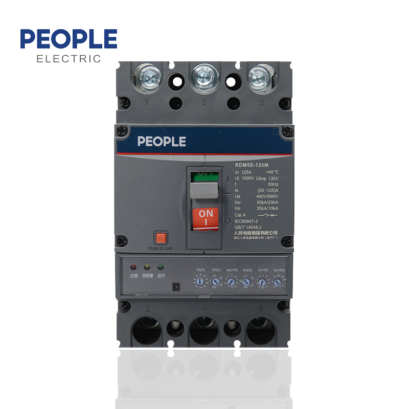
RDM5E series Electronic MCCB is applied to power distribution network of AC50/60Hz, Rated operate voltage up to 690, Rated current up to 800A.t ismainly used to distributing electric energy and protecting circuit and power-supply device against the faults of overload, shor-circuit and under-voltage.And it also can works for transfering circuit and starting motor unfrequently. MCCB has protect functions of overload longtime-delay inverse timeimit, shor-circuit shor-ime delay inverse time limit, short-circuit shor-time constant time-ag, shor-circuit instantaneous and undervoltage. This producihas advantages of small volume, high breaking capacity, short-arc, accessory easy install, anti-vibration.This product conforms to standard of IEC60497-21
| Selection Guide | ||||||||||||||
| RDM5E | 125 | M | P | 4 | 4 | 0 | 2 | Z | R | |||||
| Product code | Frame Size | Breaking capacity | Operation mode | Poles | Release mode | Accessories code | Use code | Product category | Wiring mode | |||||
| Electronic molded casecircuit breaker |
125 250 400 800 |
M: Medium breaking type H: High breaki ng type |
No code: handledirect operation Z. Turn handle operation P: Electric operation |
3:3 poles 4:4 poles |
Release mode code 4: Electronicrelease |
See Table1 for accessory code | No code: circuit breaker for distribution 2: Circuit breaker for motor protection |
No code: basic type Z: Intelligent communication type 10:Fire protection type |
No code: front-plate wiring R: wiring behind the board PF: plug-in front-plate wiring PR: plug-in rear-plate wiring |
|||||
| Remarks: | ||||||||||||||
| 1) It has overload thermal memory function: overload thermal memory function, short circuit (short time delay) thermal memory function. 2) Communication function: standard RS485 interface, Modbus field bus protocol. It is realized through plug-in accessories. See the following table for the configuration of communication accessories: |
| No | Description | Accessory function | ||||||
| 1 | Communication shunt alarm accessories | Communication+shunt+overload alarm without tripping+reset button+work indication | ||||||
| 2 | Status feedback communication attachment | Four remote communication+reset button+work indication | ||||||
| 3 | Prepayment attachment | Prepayment control+work instructions | ||||||
| Parameters | |||||||||||
| Rated current of shell frame grade Inm (A) | 125 | 250 | 400 | 800 | |||||||
| Rated current In (A) | 32、63、125 | 250 | 400 | 630、800 | |||||||
| Current setting value IR (A) | (12.5~125)+Close | (100~250)+Close | (160~400)+Close | (250~800)+Close | |||||||
| Breaking capacity level | M | H | M | H | M | H | M | H | |||
| Number of poles | 3P、4P | ||||||||||
| Rated frequency (Hz) | 50 | ||||||||||
| Rated insulation voltage Ui (V) | AC1000 | ||||||||||
| Rated impulse withstand voltage Uimp (V) | 12000 | ||||||||||
| Rated working voltage Ue (V) | AC400/AC690 | ||||||||||
| Arcing distance (mm) | ≤50 | ≤50 | ≤100 | ≤100 | |||||||
| Short-circuit breaking capacity level | M | H | M | H | M | H | M | H | |||
| Rated limit short-circuit brea king capacity Icu (kA) |
AC400V | 50 | 85 | 50 | 85 | 65 | 100 | 75 | 100 | ||
| AC690V | 35 | 50 | 35 | 50 | 42 | 65 | 50 | 65 | |||
| Rated operating short-circui t breaking capacity Ics (kA) |
AC400V | 20 | 20 | 20 | 20 | 20 | 20 | 20 | 20 | ||
| AC690V | 10 | 10 | 10 | 10 | 15 | 15 | 15 | 15 | |||
| Rated short-time withstand current Icw (kA/1s) |
1.5 | 3 | 5 | 10 | |||||||
| Use category | A | A | B | B | |||||||
| Compliance with standards | IEC60497-2/GB/T14048.2 | ||||||||||
| Applicable working ambient temperature | -35℃~+70℃ | ||||||||||
| Electrical life (times) | 8000 | 8000 | 7500 | 7500 | |||||||
| Mechanical life (times) | 20000 | 20000 | 10000 | 10000 | |||||||
| Front panel connection | █ | █ | █ | █ | |||||||
| Back panel connection | █ | █ | █ | █ | |||||||
| Plug-in wiring | █ | █ | █ | █ | |||||||
| Undervoltage release | █ | █ | █ | █ | |||||||
| Shunt release | █ | █ | █ | █ | |||||||
| Auxiliary contact | █ | █ | █ | █ | |||||||
| Alarm contact | █ | █ | █ | █ | |||||||
| Electric operating mechanism | █ | █ | █ | █ | |||||||
| Manual operating mechanism | █ | █ | █ | █ | |||||||
| Intelligent control module | █ | █ | █ | █ | |||||||
| Test power module | █ | █ | █ | █ | |||||||
| Communication function | █ | █ | █ | █ | |||||||
| Time setting | █ | █ | █ | █ | |||||||
| Dimensions | ||||||||||||||
| See Figure 1 for the overall dimensions of the front-plate wiring (X-X and Y-Y are the center of the circuit breaker) |
To learn more please click:https://www.people-electric.com/rdm5e-series-moulded-case-circuit-breaker-electronics-mccb-product/
Post time: Apr-01-2025


