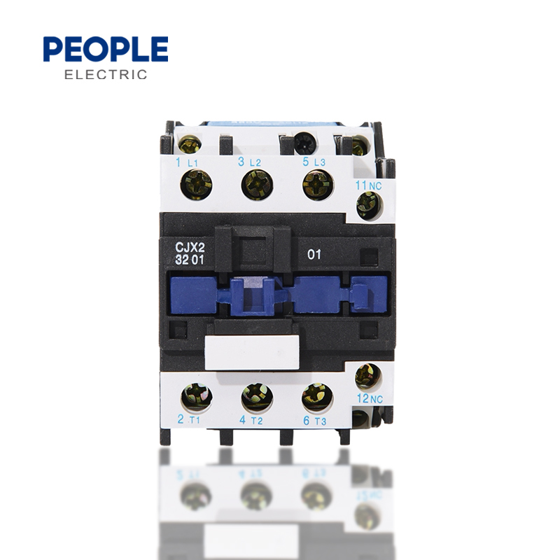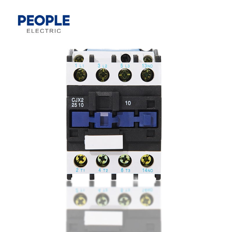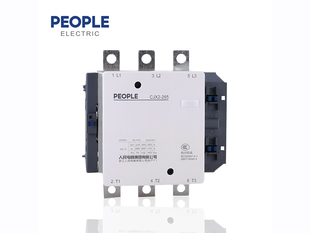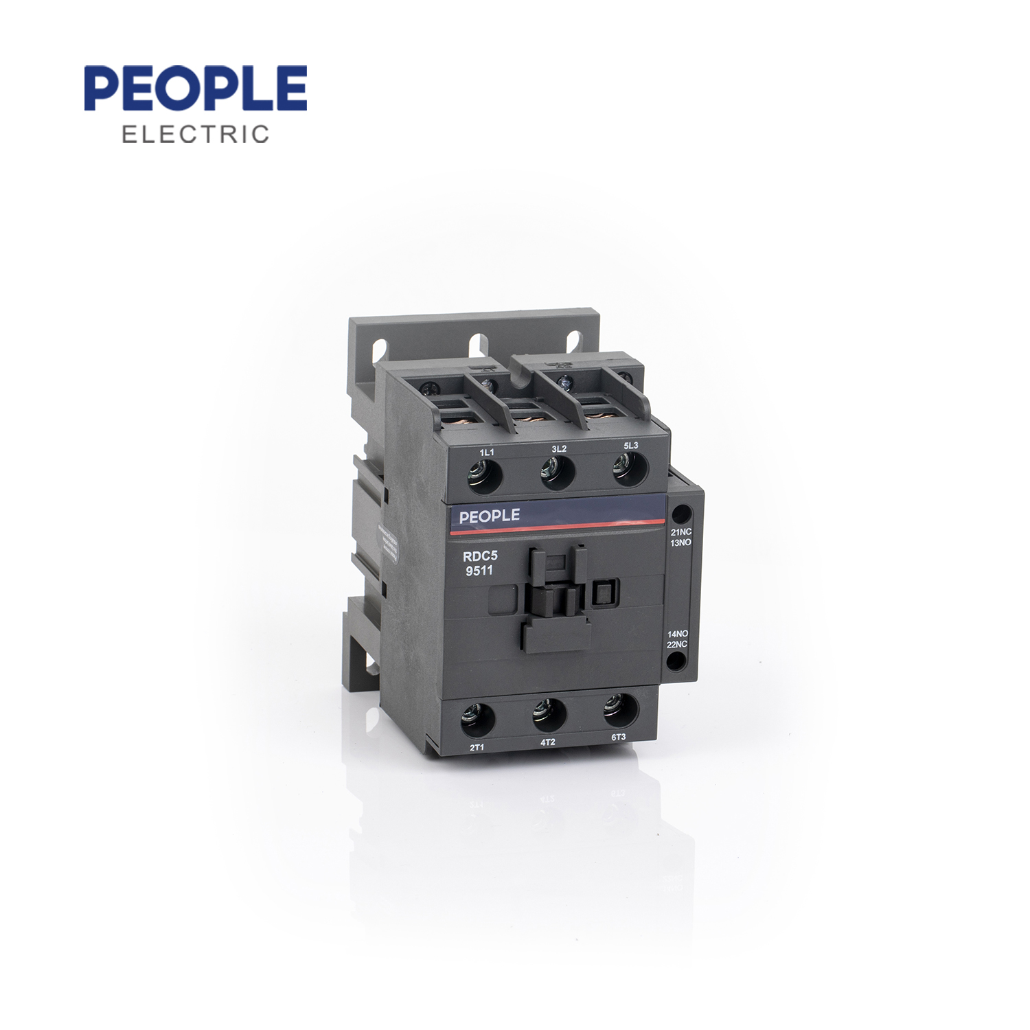
CJX2 series AC Contactor is mainly used in the circuit of AC 50Hz or 60Hz, rated voltage up to 690Vrated current up to 95A, for the use of remotely connecting and breaking the circuit, it also can bedirectly combined with thermal relay into electromagnetic starter to protect the circuit that may haveoverloaded operations, Contactor can also be equipped with accessories such as the block typeauxiliary contacts group, air delay contact, mechanica interlock mechanism, etc. to combine intodelay contactor, directional contactor, and star-delta starter. lt conforms to the standardIEC/EN60947-4-1
Normal operating condition and installation condition
1. Ambient temperature: +5°C~+40°C, average temperature within 24h does not exceed +35°C;
2. Altitude: does not exceed 2000m.
3. Atmospheric condition: when the highest temperature is +40°C, the relatively humidity does not exceed 50%; It can allow relatively high humidity when It is at relatively low temperature, for instance, it reaches 90% when it is at +20°C , it should take measurement when there have condensation occurred due to the temperature variation.
4. Pollution grade: 3.
5. Installation category: III.
6. Installation position: the gradient of the mounting surface to the vertical surface does not exceed ±5°
7. Impact and vibration: product should be installed and used at the places without obvious shake, impact and vibration.
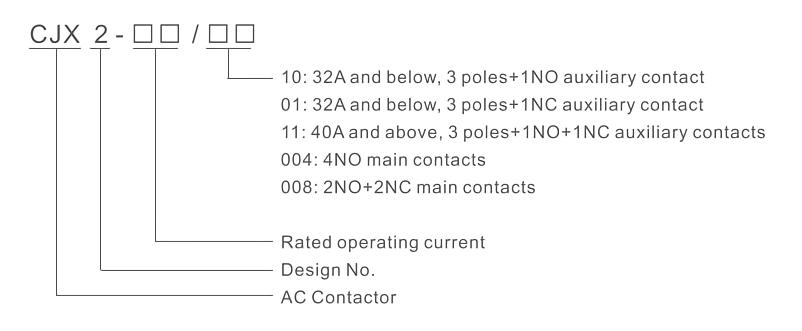
Model No.
Main technique parameter
Main technique parameter of contactor to see table 1
Model | CJX2-09 | CJX2-12 | CJX2-18 | CJX2-25 | CJX2-32 | CJX2-40 | CJX2-50 | CJX2-65 | CJX2-80 | CJX2-95 | |||
Rated insulation voltage V | 690 | ||||||||||||
Main contacts | Conventional heating current(≤40°C) A | 20 | 20 | 32 | 40 | 50 | 60 | 80 | 80 | 125 | 125 | ||
Rated current (A) when at 380V |
AC-3 | 9 | 12 | 18 | 25 | 32 | 40 | 50 | 65 | 80 | 95 | ||
AC-4 | 4 | 5 | 7 | 10 | 13 | 16 | 20 | 25 | 32 | 45 | |||
Power of controllable single phase motor kW |
110V | 0.4 | 0.5 | 0.75 | 1.1 | 1.5 | 1.5 | 2.2 | 3.7 | - | - | ||
220V | 0.75 | 1.1 | 1.5 | 2.2 | 3 | 3.7 | 5.5 | - | - | - | |||
Power of controllable three- phase squirrel cage type motor kW (when AC-3) | 220V | 2.2 | 3 | 4 | 5.5 | 7.5 | 11 | 15 | 18.5 | 22 | 25 | ||
380V | 4 | 5.5 | 7.5 | 11 | 15 | 18.5 | 22 | 30 | 37 | 45 | |||
440V | 4 | 5.5 | 7.5 | 11 | 15 | 22 | 30 | 37 | 45 | 45 | |||
660V | 5.5 | 7.5 | 9 | 15 | 18.5 | 30 | 33 | 37 | 45 | 45 | |||
AC-1 (≤40°C) A | 20 | 20 | 32 | 40 | 50 | 60 | 80 | 80 | 125 | 125 | |||
Connecting max. current A | 250 | 250 | 300 | 450 | 550 | 800 | 900 | 1000 | 1100 | 1200 | |||
Breaking max. current A | 440V | 250 | 250 | 300 | 450 | 550 | 800 | 900 | 1000 | 1100 | 1200 | ||
500V | 175 | 175 | 250 | 400 | 480 | 800 | 900 | 1000 | 1100 | 1200 | |||
660V | 85 | 85 | 120 | 180 | 200 | 400 | 500 | 630 | 640 | 700 | |||
Operation frequency | Electrical life | AC-4 | 300 | 300 | 300 | 150 | 150 | 150 | 150 | 150 | 150 | 150 | |
AC-3 | 2400 | 2400 | 1200 | 1200 | 1200 | 1200 | 1200 | 1200 | 1200 | 600 | |||
Mechanical life (times/h) | 3600 | ||||||||||||
Electrical life (10000 times/h) | AC-4 | 20 | 20-15 | 20~7 | 15~7 | 15~7 | 10~7 | 7 | 7~6 | 7~5 | 7~5 | ||
AC-3 | 200 | 160 | |||||||||||
Mechanical life (10000 times/h) | 2000 | 1000 | |||||||||||
Coil | Rated control power voltage Us (V) | AC 36, 48, 110, 220, 380, 415, 440, 660 | |||||||||||
Pull-in voltage 50/60HzV | (0.85-1.1)Us | ||||||||||||
Release voltage 50/60Hz V | (0.2~0.7)Us | ||||||||||||
Coil power | 50Hz | Pull-in VA | 70 | 70 | 70 | 110 | 110 | 200 | 200 | 200 | 200 | 200 | |
Hold VA | 8 | 8 | 8 | 11 | 11 | 20 | 20 | 20 | 20 | 20 | |||
60Hz | Pull-in VA | 80 | 80 | 80 | 115 | 115 | 200 | 200 | 200 | 200 | 200 | ||
Hold VA | 8 | 8 | 8 | 11 | 11 | 20 | 20 | 20 | 20 | 20 | |||
Power W | 1.8-2.7 | 1.8-2.7 | 1.8-2.7 | 3~4 | 3~4 | 6~10 | 6~10 | 6~10 | 6~10 | 6~10 | |||
Power | Connecting | 0.8 | 0.6 | ||||||||||
factor | Breaking | 0.3 | 0.3 | ||||||||||
Pull-in time m s | 12~22 | 15-24 | 20-26 | 20-35 | |||||||||
Release time m s | 4~12 | 5~19 | 8~12 | 6~20 | |||||||||
Max. operating frequency | 3500 times/h | ||||||||||||
Terminal | Pieces | 1 2 | 1 2 | 1 2 | 1 2 | 1 2 | 1 2 | 1 2 | 1 2 | 1 2 | 1 2 | ||
Flexible wire with cold-press terminal (mm2) | 2.5 | 2.5 | 4 | 4 | 6 | 10 | 16 6 | 16 6 | 50 25 | 50 25 | |||
Flexible wire without cold-press terminal(mm2) | 4 | 4 | 6 | 10 6 | 10 6 | 16 | 25 16 | 25 16 | 50 35 | 50 35 | |||
Single hard wire | 4 | 4 | 6 | 6- | 10 | 10 | 25- | 25- | 50- | 50- | |||
Weight (kg) | 0.32 | 0.32 | 0.35 | 0.49 | 0.55 | 1.07 | 1.07 | 1.10 | 1.44 | 1.44 | |||
Suited fuse type | Model | RDT16(NT) – 00 | |||||||||||
Rated current (A) | 20 | 20 | 32 | 40 | 50 | 63 | 80 | 80 | 100 | 125 | |||
Auxiliary contacts | Can be added with F4, LA2-D/LA3-D type air delay contacts |
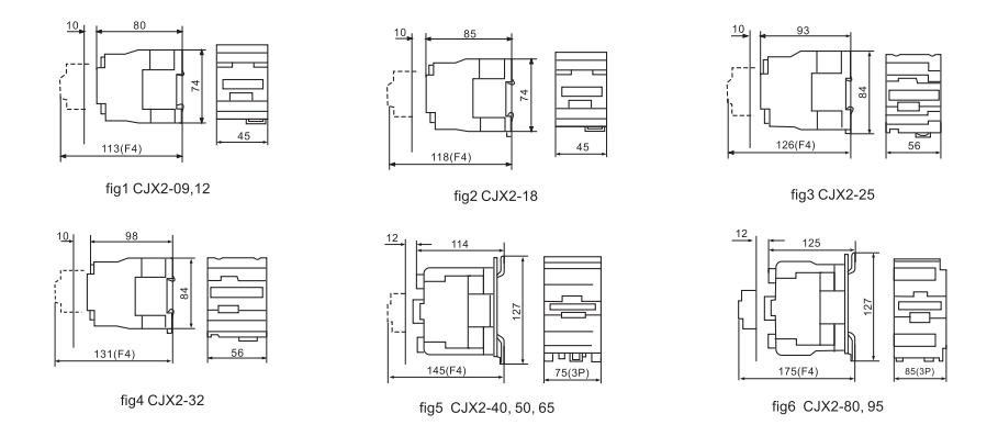
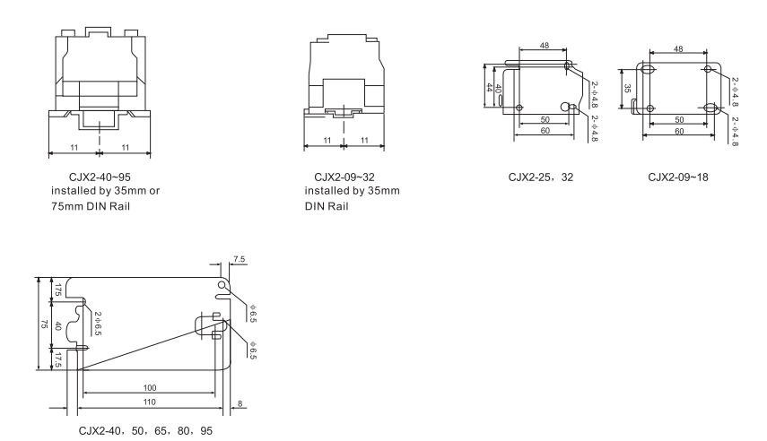
Shape and installation dimensions